Ultimate UML Books Collection
What is UML (Unified Modeling Language)?
UML, short for Unified Modeling Language, is a standardized modeling language consisting of an integrated set of diagrams, developed to help system and software developers for specifying, visualizing, constructing, and documenting the artifacts of software systems, as well as for business modeling and other non-software systems.
Origin of UML
- UML is a notation that resulted from the unification of OMT from Object Modeling Technique (OMT) and Object-Oriented Software Engineering (OOSE)
- The goal is to provide a standard notation that can be used by all object-oriented methods and to select and integrate the best elements of precursor notations
- Designed for a broad range of applications: distributed systems, analysis, system design and deployment, etc.
History of UML
- During 1996, the first Request for Proposal (RFP) issued by the Object Management Group (OMG) provided the catalyst for these organizations to join forces around producing a joint RFP response
- This collaboration produced UML 1.0, a modeling language that was well-defined, expressive, powerful, and generally applicable
- In January 1997 IBM, ObjecTime, Platinum Technology, Ptech, Taskon, Reich Technologies and Softeam joined the UML partners to contribute their ideas, and together the partners produced the revised UML1.1 response
Why UML?
- Provide users with a ready-to-use, expressive visual modeling language so they can develop and exchange meaningful models
- Be independent of particular programming languages and development processes
- Encourage the growth of the OO tools market
- Support higher-level development concepts
- Integrate best practices
Ultimate UML resources – Books, Lectures, Handouts
Listed below is a full collection of UML resources that help you learn more about UML.
Introduction to UML
UML is a standard language for specifying, visualizing, constructing, and documenting the artifacts of software systems.
For a full collection of UML books, lectures, handout and presentations, click here.
Use case diagram
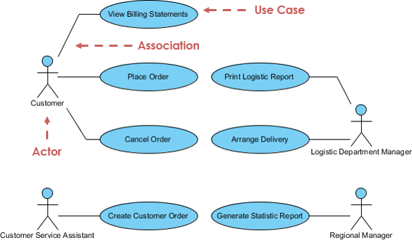
A use-case model describes a system’s functional requirements in terms of use cases. It is a model of the system’s intended functionality (use cases) and its environment (actors). Use cases enable you to relate what you need from a system to how the system delivers on those needs.
Click here to visit our UML use case diagram book collection.
Sequence diagram
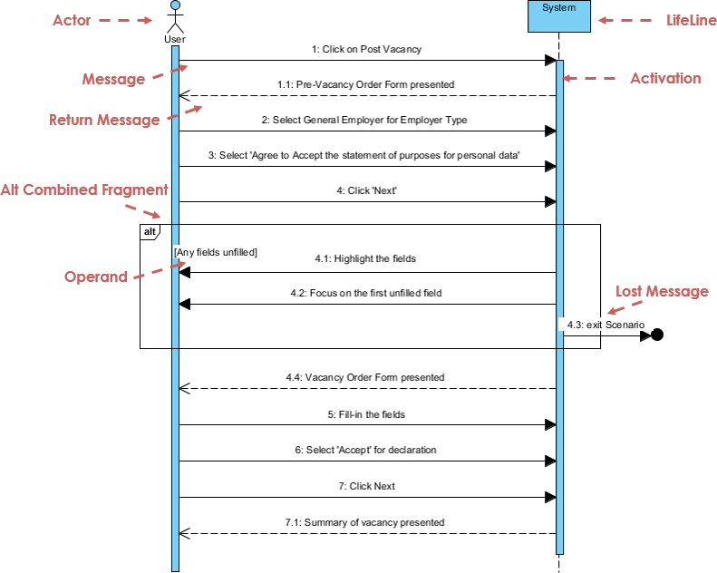
The Sequence Diagram models the collaboration of objects based on a time sequence. It shows how the objects interact with others in a particular scenario of a use case. With the advanced visual modeling capability, you can create complex sequence diagram in few clicks. Besides, some modeling tool such as Visual Paradigm can generate sequence diagram from the flow of events which you have defined in the use case description.
Click here to visit our UML sequence diagram book collection.
Class diagram
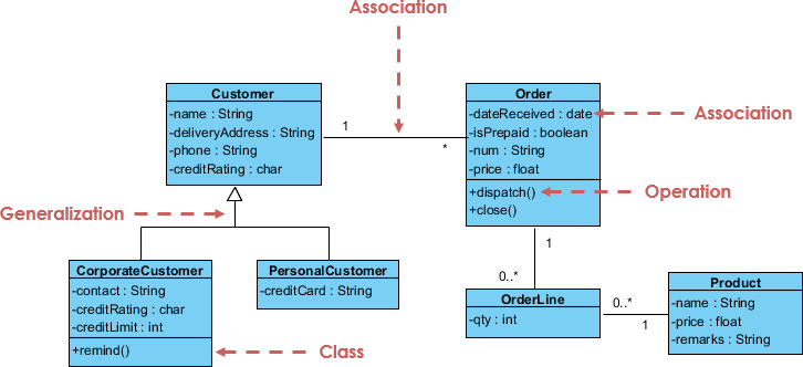
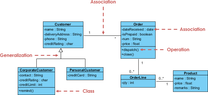
The class diagram is a central modeling technique that runs through nearly all object-oriented methods. This diagram describes the types of objects in the system and various kinds of static relationships which exist between them.
Click here to visit our UML class diagram book collection.
State machine diagram
A state diagram is a type of diagram used in UML to describe the behavior of systems which is based on the concept of state diagrams by David Harel. State diagrams depict the permitted states and transitions as well as the events that effect these transitions. It helps to visualize the entire lifecycle of objects and thus help to provide a better understanding of state-based systems.
Click here to visit our UML state machine diagram book collection.
Activity diagram
Activity diagrams are graphical representations of workflows of stepwise activities and actions with support for choice, iteration and concurrency. It describes the flow of control of the target system, such as the exploring complex business rules and operations, describing the use case also the business process. In the Unified Modeling Language, activity diagrams are intended to model both computational and organizational processes (i.e. workflows).
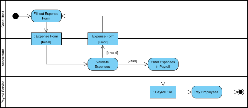
Click here to visit our UML activity diagram book collection.
Package diagram
Package diagram is UML structure diagram which shows packages and dependencies between the packages.
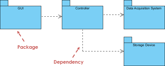
Click here to visit our UML package diagram book collection.
Deployment diagram
The Deployment Diagram helps to model the physical aspect of an Object-Oriented software system. It is a structure diagram which shows architecture of the system as deployment (distribution) of software artifacts to deployment targets.
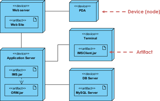
Click here to visit our UML deployment diagram book collection.
Component diagram
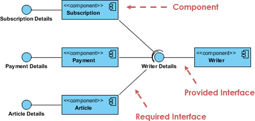
In the Unified Modeling Language, a component diagram depicts how components are wired together to form larger components or software systems. It illustrates the architectures of the software components and the dependencies between them. Those software components including run-time components, executable components also the source code components.
Click here to visit our UML component diagram book collection.
Communication diagram
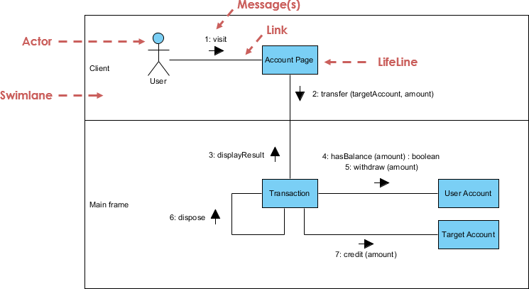
Similar to Sequence Diagram, the Communication Diagram is also used to model the dynamic behavior of the use case. When compare to Sequence Diagram, the Communication Diagram is more focused on showing the collaboration of objects rather than the time sequence. They are actually semantically equivalent, so some of the modeling tool such as, Visual Paradigm allows you to generate it from one to the other.
Click here to visit our UML communication diagram book collection.
Timing diagram
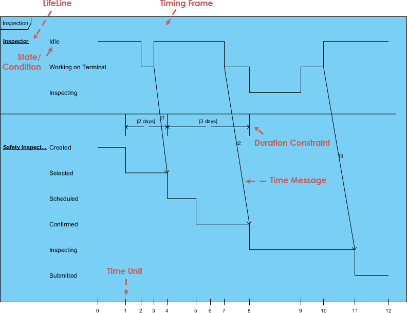
Timing Diagram shows the behavior of the object(s) in a given period of time. Timing diagram is a special form of a sequence diagram. The differences between timing diagram and sequence diagram are the axes are reversed so that the time are increase from left to right and the lifelines are shown in separate compartments arranged vertically.
Click here to visit our UML timing diagram book collection.
Interaction overview diagram
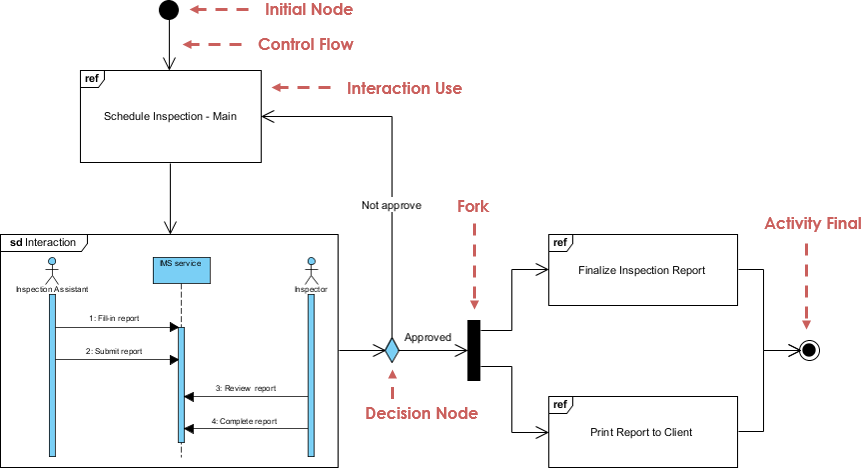
The Interaction Overview Diagram focuses on the overview of the flow of control of the interactions. It is a variant of the Activity Diagram where the nodes are the interactions or interaction occurrences. The Interaction Overview Diagram describes the interactions where messages and lifelines are hidden. You can link up the “real” diagrams and achieve high degree navigability between diagrams inside the Interaction Overview Diagram.
Click here to visit our UML interaction overview diagram book collection.
